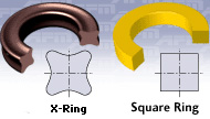
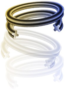
Quad-Ring® Brand Seals for Static and Non-Rotary Dynamic Applications
Cross-section.
Select a Quad-Ring® Brand cross-section size from the available standard sizes. If you are unsure what cross-section size to use, see here.
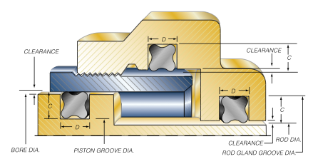
Clearance.
Determine the maximum clearance present in your application. For a radial seal, subtract the minimum rod (shaft) diameter from the maximum bore diameter. For a face seal, subtract the distance between the sealing surface and the mating surface.
Check the Clearance.
Determine if the clearance is acceptable for the application pressures and the material hardness being used by checking the graph here. Minnesota Rubber and Plastics standard-line products are made from materials having a hardness of 70 Shore A. If the clearance is unacceptable, component tolerance will have to be tightened, a harder material will have to be special ordered, or a back-up ring will have to be used.
Note: The graph provides clearance values as radial values, so divide the number obtained in the preceding step by 2 to obtain your radial clearance.
Calculate the Quad-Ring® Brand groove dimensions.
Using the table above, determine the maximum recommended gland depth for your application. Then, calculate the Quad-Ring® Brand groove diameter as follows: a.For a rod (shaft) seal:
Quad-Ring® Brand Groove Diameter = Min Shaft Diameter + (2 X Recommended Gland Depth) b.For a bore (piston) seal:
Quad-Ring® Brand Groove Diameter = Max Bore Diameter - (2 X Recommended Gland Depth) c.For a face seal:
Quad-Ring® Brand Groove Depth = Recommended Gland Depth - Application Clearance
With a face seal, if the two surfaces to be sealed are in direct contact (such as with a cover), the seal groove
depth is simply the Recommended Gland Depth
Groove Width.
Refer to the table above to determine the groove width for the Quad-Ring® Brand cross-section size you have selected. If you are using a back-up ring in your application, increase the groove width by the maximum thickness of the back-up ring.
Percent Gland Fill.
Determine the maximum percent gland fill using Equation 6. If the gland fill exceeds 100%, the groove will have to be redesigned. A good "rule-of-thumb" is to not exceed about 90% gland fill.
Calculate the Seal Squeeze.
Using Equations 3 and 4, calculate the minimum and maximum seal cross-sectional compression (squeeze). The recommended gland values in the table above have been developed to create a proper range of squeeze for many applications involving oil, hydraulic fluid, or normal lubricants, providing component tolerances are sufficiently controlled. In applications involving high pressure, large component tolerances, the need for very low frictional forces, or other types of fluids, the seal and groove design should be verified through an acceptable method, such as testing or engineering analysis.
Select the Seal.
Select the proper Quad-Ring® Brand size from the Standard Size table. Start by turning to the section of the table for the cross-section size you have selected, and then finding the Quad-Ring® Brand for the proper size bore or rod (shaft) you are sealing. If the bore or shaft size you are using is not listed, select the Quad-Ring® Brand with an inside diameter just smaller than the shaft you are using. If you are designing a face seal, select the Quad-Ring® Brand with an inside diameter which will position the Quad-Ring® Brand on the side of the groove opposite the pressure. Click here for more information on face seal groove design. Note the Quad-Ring® Brand inside diameter for the next step.
Calculate the Seal Stretch.
Using Equation 1, calculate the installed seal stretch. If the installed seal stretch is greater than about 3%, you may have to select the next larger Quad-Ring® Brand size or require a custom Quad-Ring® Brand for your application. If you are using a Quad-Ring® Brand size less than a number -025, click here for more information.
Detail the Groove.
Complete the groove design by specifying the proper radii and finish as indicated in the figure above.
 Calculate the Seal Squeeze.
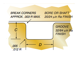 Select the Seal.